Illustration
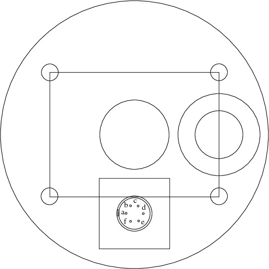
1: Base of Pump
Illustration
1: Base of Pump
Brief Data for Alcatel/Adixen/Daniels MDP-5011 Molecular Drag Pump
These are sold from time to time on E-Bay at very varying prices. I picked up a couple of these at reasonable prices. Matching inverters are also available occasionally,but I did not wish to use the standard inverter, and preferred to connect this to a PC and integrate it with the fore-vacuum and HV gauges.
The pumps are well supported by the local supplier , John Morris Scientific.
The complete electrical data for these pumps is not published, so it was necessary to take some careful measurements, the results of which are here for anyone who wishes to use them for a similar purpose (I take no responsibility whatever for the accuracy of the information,but please let me know if you find errors).
The pump has a six pin “Cannon” style connector (ITT-Cannon part No. TPV0C10B6TPN) which mates with a proprietary Alcatel cable. These connectors were a bit hard to source, so I simply used 6 gold plated single wire push fit spring connectors (Berg/DuPont PV or Electus HP1260 + heat shrink) crimped onto a 9 way ribbon cable with a crimped male “D” plug on the other end of the ribbon.
A PX139 absolute gauge was used to monitor the fore-vacuum. This latter gauge was checked using a Baratron 0-10 millibar capacitive gauge. The PX139 gauges are quite reliable and sell for ~$25 on E-Bay. Motorola MPX200A gauges are sometimes available even more cheaply. They also work very well , but require an amplifier, and are a bit harder to connect to the vacuum line. The Baratron gauges are more expensive and unnecessarily good for this application. I bought a defective Baratron gauge , and fixed it as a means to check the other gauge types. The PX139 gauge was connected to the same 5 volt supply as the position sensor and connected using a spare line in the same ribbon cable.
Pin Allocation on Cannon Connector, and Connections via Ribbon cable to 9 Pin Male “D” connector
|
Pin |
Function |
Ribbon |
Designator |
On 9 pin “D” |
|
A |
Motor winding |
1,2 |
M1 |
1,6 |
|
B |
Motor winding |
3,4 |
M2 |
2,7 |
|
C |
O/C Position Out |
7 |
POS |
4 |
|
D |
Thermistor |
8 |
THERMISTOR |
9 |
|
E |
Sensor & Thermistor Ground |
5 |
Gnd |
3 |
|
F |
5V. For sensor |
6 |
Vcc |
8 |
|
|
Forevacuum PX139 Analog Out |
9 |
PX139 |
5 |
The motor has a single pole single phase permanent magnet layout, IE at 10Hz it spins at 600 RPM. Its cold resistance is ~ 2.7 Ohm.
The position sensor operates perfectly when supplied with 5 volt DC. The open collector output allowed it to connect directly to a microcontroller running at 3.3 Volt.
I drove the motor from a sinewave inverter with all PWM filtered out. The drive signal was phase locked to the position sensor output, the offset angle must take into account the motor connections (swapping the connections shifts the phase 180 degree). The motor has a significant effective internal series reactance, allowing the drive voltage to be reduced by shifting the phase angle without significantly losing efficiency. The open circuit back-emf is around 23 V RMS at speed, and is sinusoidal.
The speed was regulated automatically to the correct value by adjusting the inverter output voltage relative to the back emf of the motor. The peak instantaneous inverter current limit was set to < 3 Amp, a value which gave plenty of control headroom. The normal operating current does not exceed half this value. For safety reasons it is very wise to put an energy absorbing over-voltage clamp (about 50V) on the supply to the inverter to absorb power during deceleration.
The motor starts reliably in the correct direction after a bit of dithering if a suitable combination of start frequency and voltage (about 1.7Hz) are applied. The pump spins to speed (27000 RPM) in a few minutes. The pumps make some bearing noise at some speeds during start-up , but run quietly at full speed. The motor current increases significantly if the forevacuum is more than a few Torr, and decreases slowly by about 20% as the motor and its bearings warm up. If the pump is to be run with a heavy gas load or a poor forevacuum for a longer period it would be necessary to use a cooling fan.
Readings taken were as follows with a forevacuum < 1 Torr. The motor power was estimated to be 90% of the DC input to the full bridge PWM inverter. The pump was mounted vertically with the outlet lowest.
|
Temperature |
DC Voltage to Inverter |
DC Current into Inverter |
RMS Motor Voltage |
DC Power Into Inverter |
Estimated Motor Power |
|---|---|---|---|---|---|
|
Cold – 24 deg Celsius |
36.0V |
0.52A |
20.0V |
18.7W |
16.8W |
|
Warm |
37.5V |
0.38A |
18.0V |
14.3W |
12.8W |
If the steady motor power is significantly higher than these figures, then the bearings need attention (either greasing or replacement). One of the pumps did not like running at speed with the inlet at the bottom, made noises, and drew more power, although it was quite quiet with the inlet on top so I suspect it may need regreasing or more serious work. This may be a way of checking bearing function. The manufacturer permits the pump to be operated vertically or horizontally, but not inclined at other than 90 degrees.
I am not including other pump information which is available from the manufacturers website or local agents. The pump has a relatively low capacity at low pressures , but operates well at a very low rotational speed, has a high pumping ratio and tolerates a very poor forevacuum. It will survive a relatively sudden collapse of the vacuum in contrast to faster pumps.
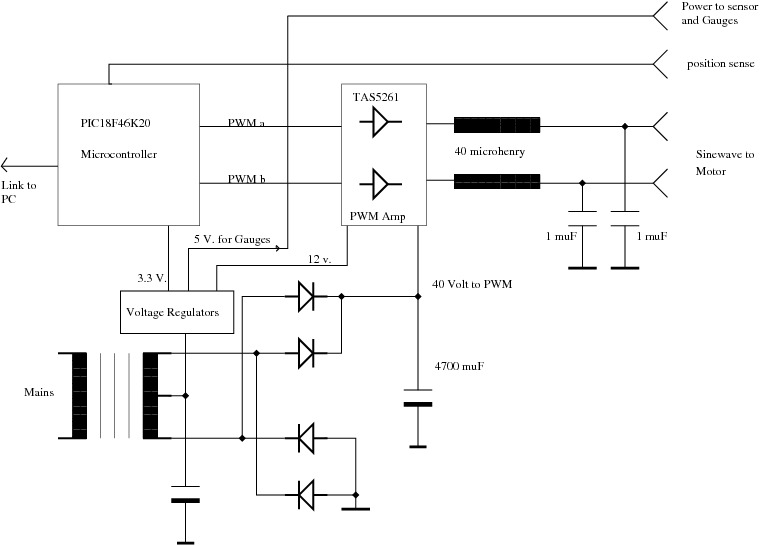
The block diagram for the pump controller is as follows. The TAS5261 incorporates a full bridge with protection circuitry, but could be replaced with 4 mosfets and two gate drivers. PWM b is an inverted copy of PWM a. The PWM frequency is 125 kHz. Since this is somewhat below the normal frequency of the TAS5261, the high side gate drive capacitors were increased to .05 muF. The outputs of various gauges etc. were connected to the analogue inputs of the PIC controller. The PIC controller was perfectly adequate for the task, but many of the "ARM" processors would be equally suitable.
The firmware for the PIC18f4520 microcontroller is written in PIC assembler Pic18pwm Assembler Source , Register Definitions , General Macros , Handshake IO via programming pins , and compiled using open source tools. The definitions for the register names and locations are in a copyright macro file published by Microchip. A copy of the file is Microchip Register Definitions , which I renamed pic4520.a18 for consistency .
![]()